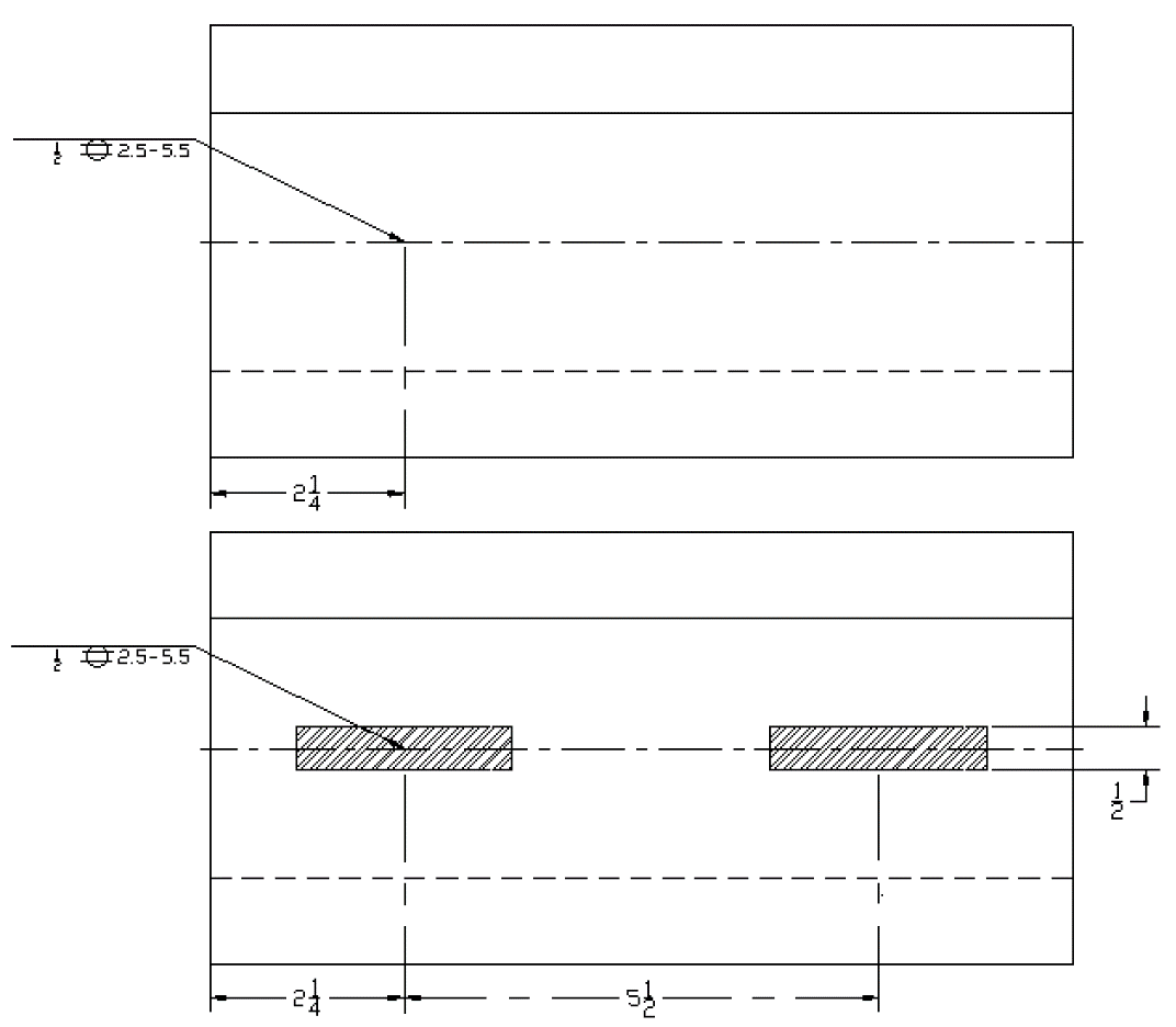
Stitch welding is spot welding in which successive welds overlap. An arrow line 2.
 Star Delta Starter Power Circuit Diagram Electrical Circuit Diagram Circuit Diagram Delta Connection
A reference line 3.

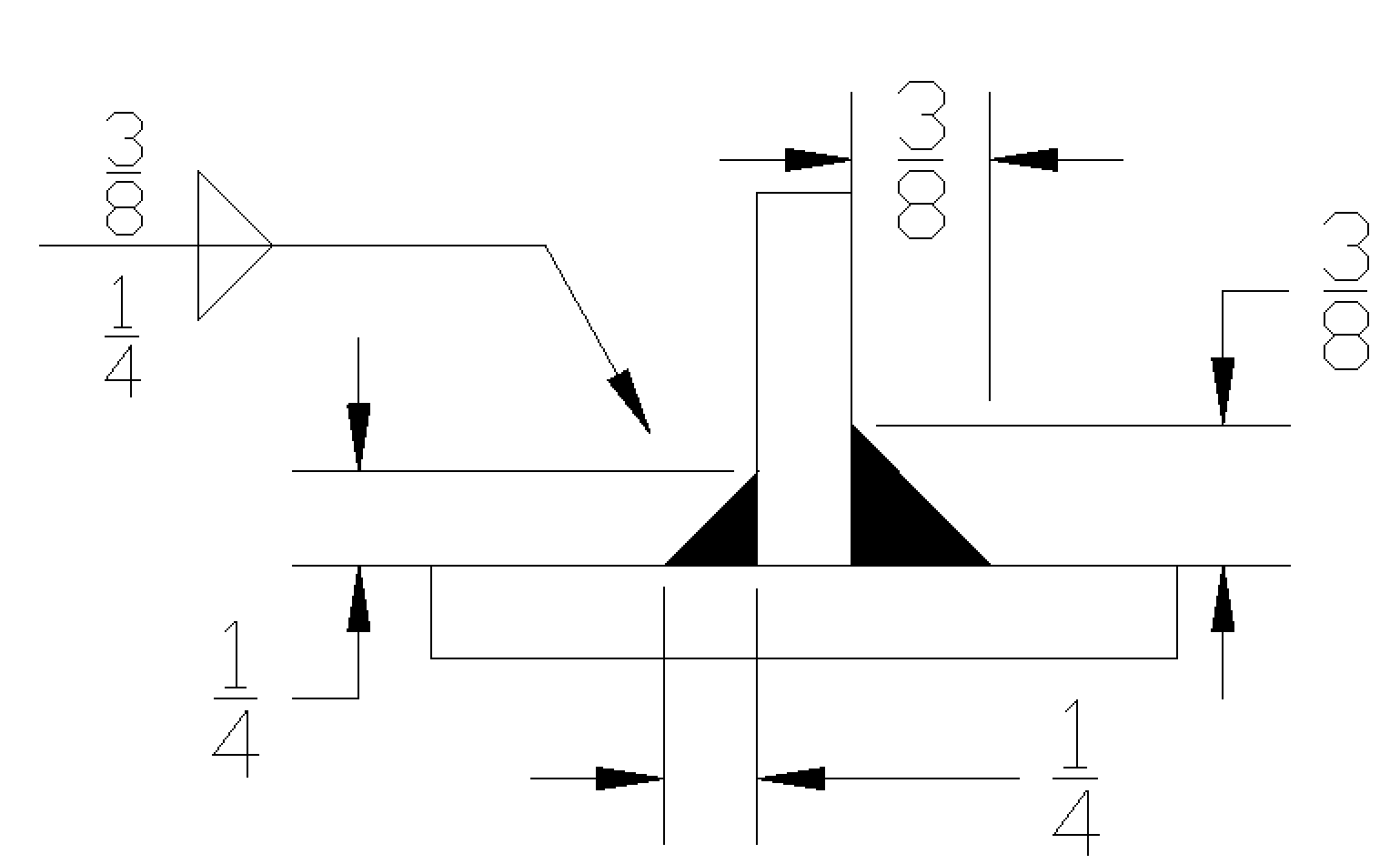
Stitch welding symbols on drawings. The weld length will be provided on the right side of the fillet weld symbol. While in the drawing environment the Weld Symbol tool can be found on the Annotation Tab. The weld symbol always includes 1.
Flare Bevel Groove Welds. The arrows of the symbol between the two letters indicate that a weld needs to run the full length between the two marks. If the weld symbol is on the bottom side the desired weld seam must be placed on the arrow side.
Cruciform joint where the top weld is on the arrow side and the bottom weld is on the other side The positioning of the symbol is the same for drawings in first or third angle projectionAdditional symbols can be added to the reference line as shown in Fig. It is essential that everyone should have a full understanding of weld symbol requirements to ensure that the initial design requirement is met. Overall there are three different possible positions for a weld symbol in the welding symbol.
Reference line arrow basic weld symbols dimensions and other data supplementary symbols finish symbols tail and specification process or other reference. Concave welds are rarely used. There may be times where a length is given on a part and the location of the weld will be given with a dimension in order to achieve the correct location.
26 factory or on. The assembled welding symbol consists of the following eight elements or any of these elements as necessary. The contour symbol is placed above or below the weld symbol.
Superscript 2 and 3 show two of the welding symbols. Drawing Page Drawing of Weld Symbols Standards The British Standard for weld symbols is BS EN 22553. To create welding symbols and annotations that update when the model welding symbol and annotations change right-click a drawing view and click Get Model Annotations and then select Get Welding Symbols.
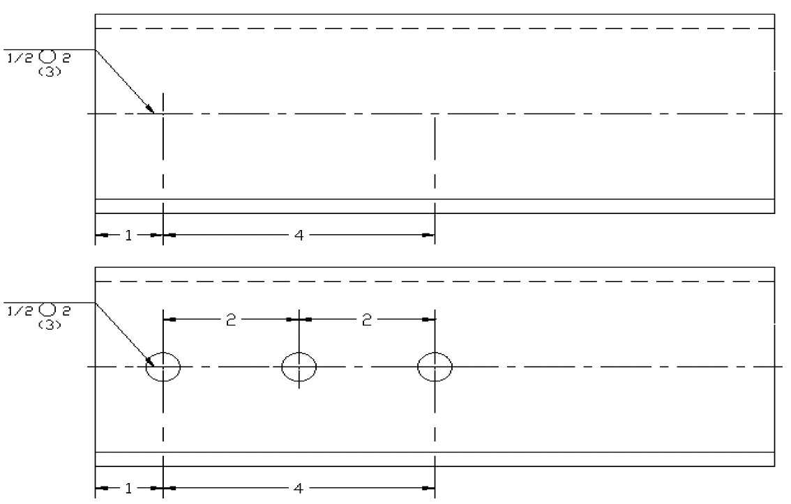
3102020 A circle in the weld symbol in drawings indicates the Around option has been used. 3-2 is a method of representing the weld symbol on drawings. Stitch welds are staggered on both sides of the welded part.
Detail drawings shall clearly indi-cate by welding symbols or sketches the details of groove welded joints and the preparation of material re-quired to make them. The welding symbol fig. An arrow line 2.
Flare V Groove Welds. A dashed line 4. This symbol has a flag showing the weld needs to be done on site not in the workshop.
The weld symbol is now finished and will be. 342019 The opposite side is the other side. Name Double sided V butt Double sided bevel butt Double sided U butt weld Symbol.
Name Weld between points Weld on site Staggered. Subcontractors are often required to interpret weld symbols on engineering drawings from perhaps the main contractor or client to determine the type of weld needed. 5112009 Contour and Finish Symbols.
A reference line 3. 12282018 Weld symbols can also be made directly in drawings. If you create a manual annotation or welding symbol in the drawing and the model contains a welding symbol or annotation the drawing welding symbol or annotation is a copy and does not update.
The following finish symbols indicate the method not the degrees of finish. Basic Weld Symbol The weld symbol always includes 1. This placement is important.
If the weld symbol is on the top side weld seam has to be placed on the other side. Hatching lines may be used to indicate the length. If you allow the rest of the symbols we can build our own AWS welding symbols through the annotation arrow and it will we work.
When identification of the weld process is required as part of the weld symbol the relevant weld process code is listed in BS EN ISO 4063. Here is a selection of basic symbols to learn as a first step. It may be left in its original state convex.
ˇˆˇ ˇ ˆ ˇˇˆ. Name Finish Weld Symbol on Symbol base platform weld. Both width and thickness of steel backing shall be detailed.
Tekla Structures shows the weld type symbols as staggered in weld symbols. All you have to do is open up the rest of the unicode for the WeldSymbol Font. This shows a 6 fillet weld to be applied to the arrow side.
Convex Concave and Flat Welds. The weld symbol is placed by clicking on the desired location of the weld. When the weld symbol hangs below the reference line it indicates that the weld must be performed on the arrow side of the joint.
Indicates where the weld should be made. The weld symbol may also be placed above the reference line rather than below it. Weld symbols on the full reference line relates to welds on the near side of the plate being welded.
Weld symbols on the dashed line relates to weld. Name Fillet Resistance Spot Resistance Steam. Set this option to Yes to create a staggered intermittent weld.
The finish symbol always appears above or below the contour symbol. Consumable insert entirely around Symbol on base platform weld. 1132021 Weld between points.
The same dialog box as found in the part environment is used to create the symbols. The drawing will show two points like an X and a Y for example between sections needing welding. 352021 The three weld symbols you see in the drawings above represent a square fillet and V-groove weld respectively.
Click on image to open larger drawing in new window Weld finishes contour With butt welds the welding symbol will tell you the final finish or contour It may be ground off flush. It is recommended that contract de-sign drawings show complete joint penetration or partial.
 View Crystal Balustrade In 2021 Crystals Views Architecture
 Pin On Le Garden
 Engineering Drawing Weld Symbols Page 1 Line 17qq Com
 Pin On Cycloid Drawing Machine
 Pin On Civil Engineering
 Spot Seam Stud Welding Symbols Interpretation Of Metal Fab Drawings
 Spot Seam Stud Welding Symbols Interpretation Of Metal Fab Drawings
 Mis Understanding Welding Symbols Part 2 American Welding Society Education Online
 Pin On Free Cad Blocks Drawings Download Center
Neufert Architects Data Ed 3 Ernst Neufert Peter Neufert Free Download Borrow And Streaming Internet Archive Architect Data Architect Data
 Fillet Weld Symbols Interpretation Of Metal Fab Drawings
 Addition Elevations Not All Drawings Have To Be Computer Generated These Elevations Are Packed With Clear Relevan Elevation Drawing Wood Railing Porch Patio
 Measuring Ruler Worksheet Sgadi New Best S Of Reading A Ruler How To Read Measurements Ruler Text Features Worksheet Reading Skills Worksheets Reading A Ruler
 Solidworks Tutorial Welding Symbol Youtube