You can see the actual weld in the second depiction. Feature works great on the assembly but dose not show on the drawing.
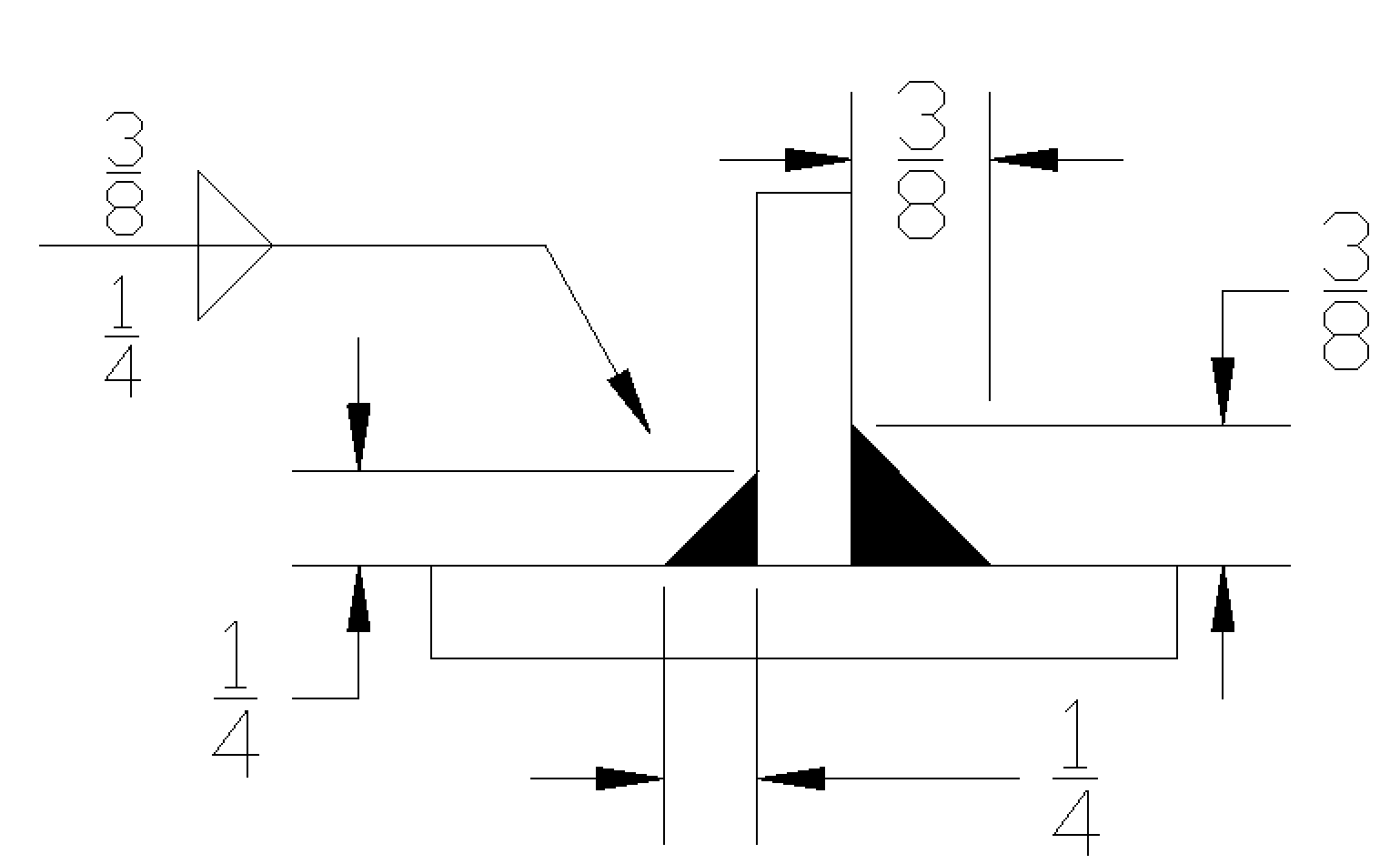 Fillet Weld Symbols Interpretation Of Metal Fab Drawings
When identification of the weld process is required as part of the weld symbol the relevant weld process code is listed in BS EN ISO 4063.

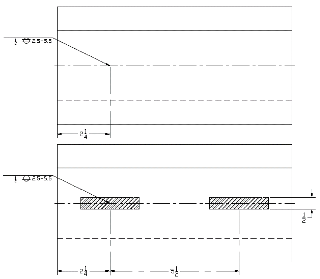
How to show stitch weld on drawing. BS 499 and AWS require symbols to be placed above the reference line which indicate the other side or below the reference. I am having to actually model in all the weld beads and save weld1 weld2 weld3 ect to achive this. 10132013 I like to show the weld bead in the assembly and in the drawing.
The eight elements which may appear in a welding symbol are- reference line arrow basic weld symbols dimensions and other data supplementary symbols finish symbols tail and specification and process or other reference. Welds and weld marks can be controlled separately. Thanks for taking the time to answer back.
3202017 OK I went to A24 for a look around and here is my opinion about the staggered stitch welds tolerance. For example In the next drawing a fillet weld is specified on the arrow side. Stitch welds are characterized by a spacing between each weld.
You can use several types of weld annotations and symbols in a drawing. This engineering drawing present weld type symbols and fillet weld symbols. Any symbol that is used to show a joint or weld type feature on the other side of the arrow line is always placed on a dotted line.
Double-click a manually created weld. The symbol is interpreted as a simplified cross-section of the weld. You can use several types of weld annotations and symbols in a drawing.
Cant seem to find anything in Help besides Caterpillars but thats just for drawing representations. We are able to get the fillets the length and the pitch but cant figure out how to offset the fillet symbol to indicate a offset weld. Click Weld Symbol Annotation toolbar or Insert.
When you create drawing views of weldment assemblies you can use the welding symbol from the model. Many of the properties are available both above and below the weld symbol line. Hold down Shift and click Weld mark on the Annotations tab.
Default appearance of weld annotations is determined by the weld symbol style and can be edited in Style and Standard Editor. Guidelines and options for adding welding symbols caterpillars and end fills. This spacing can also be referred to as pitch.
A reference line 3. A weld in which the continuity is broken by recurring unwelded spaces. 5302017 Change display style to shaded with edges.
5112009 Weld Symbols on a Drawing Refresh Your Knowledge – ANSIAWS A24-79. Default appearance of weld annotations is determined by the weld symbol style and can be edited in Style and Standard Editor. These stitches are common when welding on a long piece of material because a continuous weld is not always necessary.
For example you may want to show the welds in one drawing view view that includes selected model objects or an area in the model that is represented in a drawing A drawing view is a container for model and drawing. Then just add a note to dimension the weld size and length. 3102020 To open the weld mark properties do one of the following in an open drawing.
Model welds are displayed as weld marks and welds or weld seams in drawings. On the Drawing tab click Properties. Fillet welding refers to the process of joining two pieces of metal together whether they be.
An arrow line 2. Offset stitch weld symbol. 2212020 Fillet Weld In The Field All Around Stitch Welding Symbols.
Thats what I did and the weld shows up in the drawing. Welds are those that are not continuos in nature ie. The arrows of the symbol between the two letters indicate that a weld needs to run the full length between the two marks.
SW2006 SP31 Thanks in Advance Jeff Martin. 352021 When the weld symbol hangs below the reference line it indicates that the weld must be performed on the arrow side of the joint. When you create drawing views of weldment assemblies you can use the welding symbol from the model and automatically generate caterpillar annotations for solid body fillet welds.
Basic Weld Symbol The weld symbol always includes 1. Intermittent weld is defined under d1-1-96 as. Does anyone know how to place a weld symbol on a drawing that calls for a offset stitch fillet weld on both sides of the joint.
1132021 The drawing will show two points like an X and a Y for example between sections needing welding. I think that pretty much says you have no tolerance so have your fitters mark the effective weld lengths and be fairly accurate so the. The weld type symbol is typically placed above or below the center of the reference line depending on which side of the joint its on.
11222006 Is it possible to tweak the Insert -. Weld Bead to represent a stitch weld. Double-click an existing weld symbol or right-click the symbol and select Properties.
A544 says that the segments of staggered intermittant fillet welds SHALL BE symetrically spaced on both sides of the joint. Drawing Page Drawing of Weld Symbols Standards The British Standard for weld symbols is BS EN 22553. To open this dialog box do one of the following.
Is more or less a laymans term.
 How To Insert Weld Symbols Into A Cad Drawing Youtube
 Landscape Drawings In Pencil Pencil Landscape Cross Hatching Drawings Landscape Drawings Landscape Drawing Tutorial Line Drawing Artists
 Pin By Tammy Cochrane On Stitching Patterns Stitch Patterns Graphic Patterns Simple Graphic
 Spot Seam Stud Welding Symbols Interpretation Of Metal Fab Drawings
 Advance Steel 2021 Multi Leader Line Weld Symbol Youtube
 Solidworks Tutorial Welding Symbol Youtube
 Avalanche 41 E1469355503115 Jpg 3 037 2 304 Pixels Drift Trike Drift Trike Frame Drift Trike Motorized
 Pin By Karri Thompson On Drawing Art Art Drawings Art Drawings

Welders Cap Stencil 4 Panel Cyclist Cap Pattern 1 4 Etsy In 2021 Welder Cap Cap Patterns Welding Cap Pattern
 Solidworks Adding Weld Beads To Assemblies And Drawing Youtube
 116 Inventor Drawing Tutorial Welding Youtube
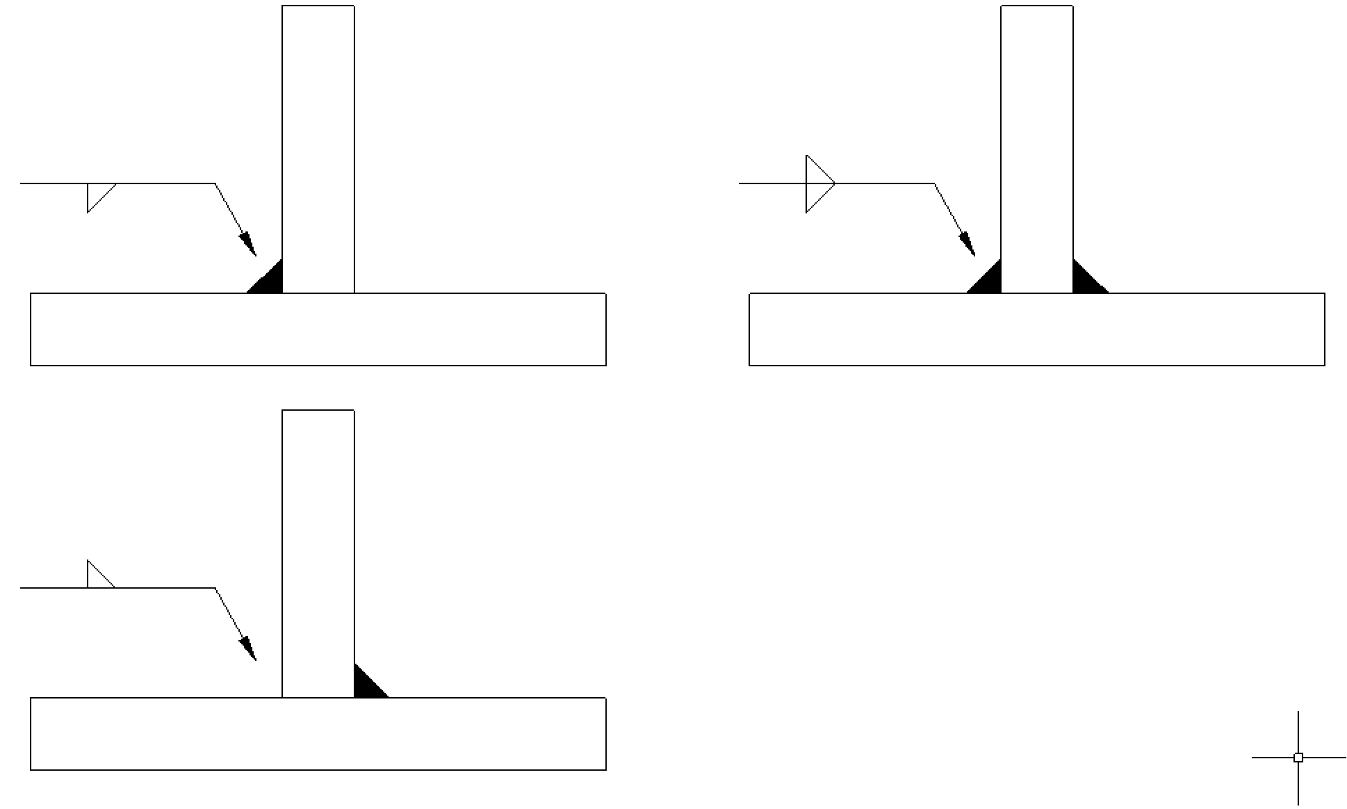 Fillet Weld Symbols Interpretation Of Metal Fab Drawings
 Coreldraw Envelope Straight Line Tool Basics The Rhinestone World Trwcd26 Coreldraw Corel Draw Tutorial Pen Tool