The finish symbol always appears above or below the contour symbol. Consumable insert entirely around Symbol on base platform weld.
 Mechanical Engineering Solution Mechanical Engineering Design Technical Drawing Mechanical Engineering
The arrows of the symbol between the two letters indicate that a weld needs to run the full length between the two marks.

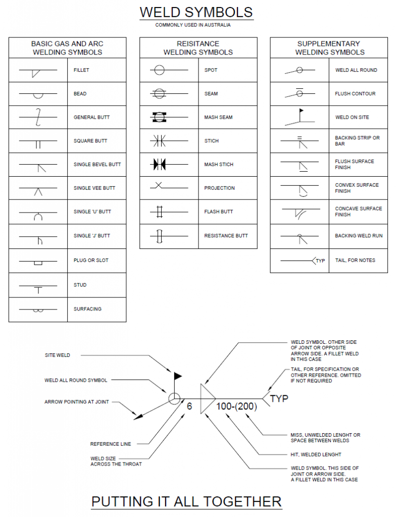
Drawing symbol for stitch weld. Name Finish Weld Symbol on Symbol base platform weld. Commonly used welding symbols and what they mean. Go here for American Welding Symbols.
Compare these two symbols. The British Standard for weld symbols is BS EN 22553. Weld symbols on the dashed line relates to weld on the far side of the plate.
This engineering drawing present weld type symbols and fillet weld symbols. Convex Concave and Flat Welds. If the dashed line is above the full line then the symbol for the nearside weld is drawn below the reference line and the symbol for the farside weld is above the dashed line.
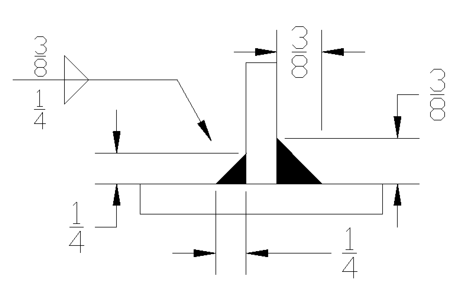
5112009 Contour and Finish Symbols. 10mm fillet weld other side of arrow. The weld type symbol is typically placed above or below the center of the reference line depending on which side of the joint its on.
6mm fillet weld arrow side. Stitch welds are staggered on both sides of the welded part. The contour symbol is placed above or below the weld symbol.
In my article on the different types of welds I showed you the 5 basic welds. Use the lower Weld Symbol button to select a symbol for an other side. If the dashed line is above the full line then the symbol for the nearside weld is drawn below the reference line and the symbol for the farside weld.
If the welds are symmetrical on both sides of the plate the dashed line is omitted. Name Double sided V butt Double sided bevel butt Double sided U butt weld Symbol. Use the upper Weld Symbol button to select a symbol for a this side.
Flare Bevel Groove Welds. Name Fillet Resistance Spot Resistance Steam. Fillet welding refers to the process of joining two.
This symbol has a flag showing the weld needs to be done on site not in the workshop. A reference line 3. 352021 The three weld symbols you see in the drawings above represent a square fillet and V-groove weld respectively.
Note what is different and what each one means. An arrow line 2. It is under the simple weld catagory option stag_fillet.
Reference line arrow basic weld symbols dimensions and other data supplementary symbols finish symbols tail and specification process. Indicates where the weld should be made. BS 499 and AWS require symbols to be placed above the reference line which indicate the other side or below the reference.
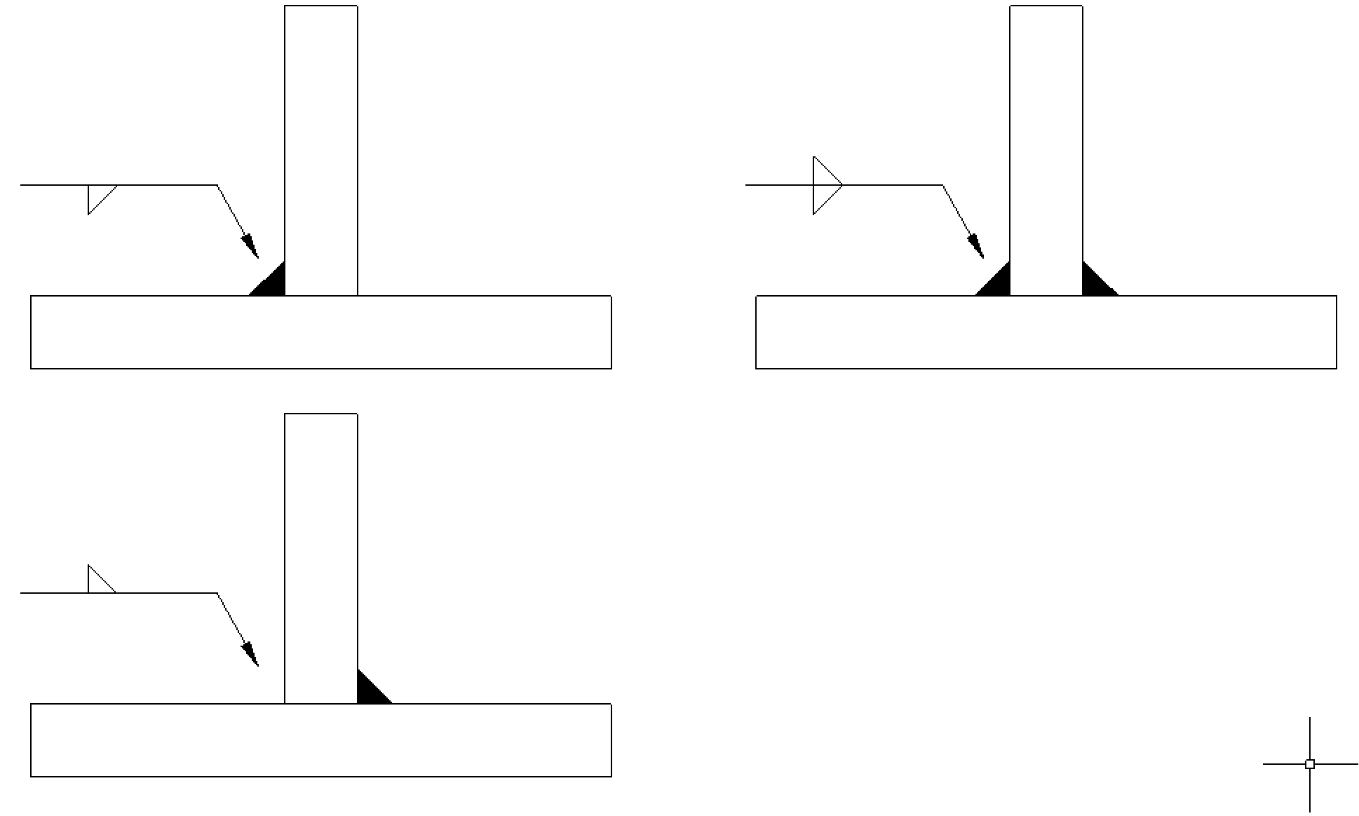
Examine the examples below which show the weld required and the symbol that conveys this information. A weld symbol is similar but different in that it is one specific symbol for one specific kind of weld. September 19 2020 Leave a Comment.
There is a specific weld symbol for each of these weld types which is just one small part of the entire welding symbol. Weld symbols on the full reference line relates to welds on the near side of the plate being welded. If the welds are symmetrical on both sides of the plate the dashed line is omitted.
Weld symbols on the dashed line relates to weld. Weld symbols on the full reference line relates to welds on the near side of the plate being welded. Set this option to Yes to create a staggered intermittent weld.
We are able to get the fillets the length and the pitch but cant figure out how to offset the fillet symbol to indicate a offset weld. 3102020 A circle in the weld symbol in drawings indicates the Around option has been used. Weld symbols on the dashed line relates to weld on the far side of the plate.
A dashed line 4. Welding symbols allow the engineer or draftsperson to communicate detailed information about the weld to the welder. The following finish symbols indicate the method not the degrees of finish.
The weld symbol always includes 1. The welding symbol consists at least of a horizontal reference line has an arrow line pointing to the joint area and can have a tail with additional information for the welding process. As used in the Australian steel fabrication industry.
Name Weld between points Weld on site Staggered. When the weld symbol hangs below the reference line it indicates that the weld must be performed on the arrow side of the joint. Any symbol that is used to show a joint or weld type feature on the other side of the arrow line is always placed on a dotted line.
Does anyone know how to place a weld symbol on a drawing that calls for a offset stitch fillet weld on both sides of the joint. 1132021 The drawing will show two points like an X and a Y for example between sections needing welding. Notes of Drawing of Welds.
An example of how to draft the weld symbols. The symbol is interpreted as a simplified cross-section of the weld. The weld symbol may also be placed above the reference line rather than below it.
The weld symbol gives you information of the type of weld and is usually a part of the welding symbol. Tekla Structures shows the weld type symbols as staggered in weld symbols. This placement is important.
Flare V Groove Welds. Download the AutoCAD DWG file of the weld symbols chart. The assembled welding symbol consists of the following eight elements or any of these elements as necessary.
Fillet groove surfacing plug and slot. 342019 The welding symbol describes the whole thing while the weld symbol can be part of the welding symbol. When identification of the weld process is required as part of the weld symbol the relevant weld process code is listed in BS EN ISO 4063.
3-2 is a method of representing the weld symbol on drawings. Click and select a symbol from a symbol. The welding symbol fig.
 Fillet Weld Symbols Interpretation Of Metal Fab Drawings
 Fillet Weld Symbols Interpretation Of Metal Fab Drawings
Terms Used With Welding Symbols Welding Table Welding Projects Welding
 Drawing And Welding Symbol Interpretation Welding Class Welding Art Welding Welding And Fabrication
 Engineering Drawing Weld Symbols Page 1 Line 17qq Com
 Korean Patterns Forty Five Symbols Symbols Pattern Hanbok
 Weldsymbols Jpg 407k Symbols Welding Cool Drawings
 Mechanical Drawing Symbols From Mechanical Engineering Valve Assembly Mechanical Engineering Design Mechanical Design Engineering Symbols
 Wallet Sized Weld Symbol Reference Card Omnia Mfg Welding And Fabrication Welding Welding Art

 Pin On Free Cad Blocks Drawings Download Center
 Blackboard Learn Flow Chart Design Process Flow Chart Flow Chart
 Weld Symbols
 Pin On Le Garden